Климат-контроль системаClimate Control System
- Auxiliary Climate Control Auxiliary Evaporator Temperature Sensor (G1779507) / Removal and Installation
- Auxiliary Climate Control Electric Booster Heater (G1779499) / Removal and Installation
- Auxiliary Climate Control Evaporator and Blower Motor Assembly (G1817039) / Removal and Installation
- Auxiliary Climate Control Fuel Fired Booster Heater Fuel Pump (G1791379) / Removal and Installation
- Auxiliary Climate Control
- Auxiliary Climate Control Electric Booster Heater
- Auxiliary Climate Control Fuel Fired Booster Heater
- Climate Control Air Conditioning Compressor - Ingenium I4 2.0l Diesel (G1885406)/ Removal and Installation
- Climate Control - Air Conditioning
 Generator and RegulatorAuxiliary Climate Control
Auxiliary Evaporator
Temperature Sensor (G1779507)
/ Removal and Installation

Дополнительный климат-контроль дополнительный Evaporator температура датчик / снятие и установкаAuxiliary Climate Control Auxiliary Evaporator Temperature Sensor (G1779507) / Removal and Installation
REMOVAL
NOTES:
- Removal steps in this procedure may contain installation details.
- Some variation in the illustrations may occur, but the essential information is always correct.
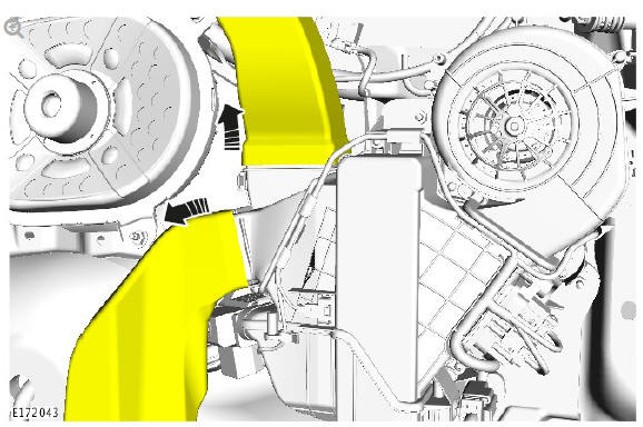
Refer to: Loadspace Trim Panel (501-05 Interior Trim and Ornamentation, Removal and Installation).


INSTALLATION
- To install, reverse the removal procedure.
- Using Land Rover approved diagnostic equipment, calibrate the sensor.
Auxiliary climate control auxilliary thermostatic expansion valve (G1779504) removal and installation
REMOVAL
NOTES:
- Removal steps in this procedure may contain installation details.
- Some variation in the illustrations may occur, but the essential information is always correct.
Refer to: Evaporator and Blower Motor Assembly (412-02 Auxiliary Climate Control, Removal and Installation).


Torque: 4 Nm
INSTALLATION
To install, reverse the removal procedure
Climate Control SystemAuxiliary Climate Control
Electric Booster
Heater (G1779499) / Removal and
InstallationДополнительный климат-контроль электрический усилитель отопитель / снятие и установкаAuxiliary Climate Control Electric Booster Heater (G1779499) / Removal and Installation
REMOVAL
NOTES:
- Removal steps in this procedure may contain installation details.
- Some variation in the illustrations may occur, but the essential information is always correct.
Disconnect the battery ground cable.
Refer to: Specifications (414-01 Battery, Mounting and Cables, Specifications).
Vehicles with automatic transmission
Refer to: Floor Console (501-12 Instrument Panel and Console, Removal and Installation).
Vehicles with manual transmission
Refer to: Gearshift Lever (308-06 Manual Transmission/Transaxle External Controls, Removal and Installation).
All vehicles
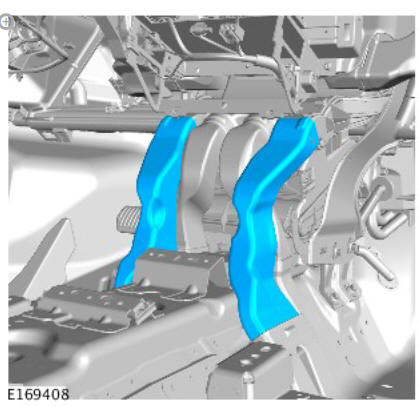


Torque: 2 Nm
Vehicles with automatic transmission
Refer to: Floor Console (501-12 Instrument Panel and Console, Removal and Installation).
Vehicles with manual transmission
Refer to: Gearshift Lever (308-06 Manual Transmission/Transaxle External Controls, Removal and Installation).
All vehicles


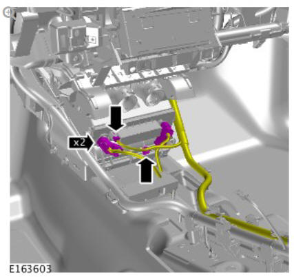
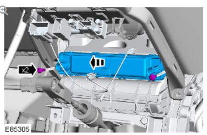
Torque: 2 Nm
INSTALLATION
To install, reverse the removal procedure.
Auxiliary Climate Control
Auxiliary Evaporator
Temperature Sensor (G1779507)
/ Removal and InstallationAuxiliary Climate Control
Evaporator and Blower
Motor Assembly (G1817039)
/ Removal and InstallationДополнительный климат-контроль Evaporator и вентилятор отопителя в сборе / снятие и установкаAuxiliary Climate Control Evaporator and Blower Motor Assembly (G1817039) / Removal and Installation
REMOVAL
NOTES:
- Removal steps in this procedure may contain installation details.
- Some variation in the illustrations may occur, but the essential information is always correct.
Refer to: Air Conditioning System Recovery, Evacuation and Charging - GTDi 2.0L Petrol (412-00 Climate Control System - General Information, General Procedures).
Refer to: Air Conditioning System Recovery, Evacuation and Charging - TD4 2.2L Diesel (412-00 Climate Control System - General Information, General Procedures).
Refer to: Wheel and Tire (204-04 Wheels and Tires, Removal and Installation).
CAUTION:
Take extra care not to damage the component.
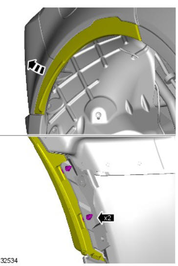
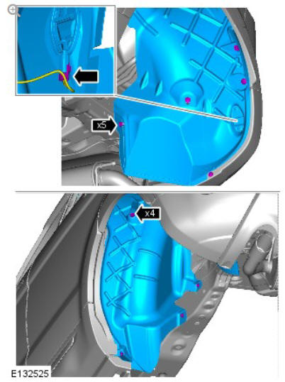

Open the rear door.

Torque: 45 Nm

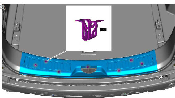


Torque: 25 Nm

NOTE:
Discard the retaining clips.

Renew Part: Retaining clips.
CAUTION:
Install new o-ring seals
NOTES:
- Remove and discard the O-ring seals.
- Make sure that all openings are sealed. Use new blanking caps.

Renew Part: Evaporator pipe O-ring seals.
Torque: 10 Nm

Torque: 5 Nm
NOTE:
Make sure that all openings are sealed. Use new blanking caps.
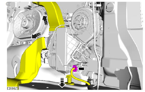

Torque: 5 Nm
INSTALLATION
To install, reverse the removal procedure.
Auxiliary Climate Control
Electric Booster
Heater (G1779499) / Removal and
InstallationAuxiliary Climate Control
Fuel Fired
Booster Heater
Fuel Pump (G1791379)
/ Removal and InstallationДополнительный климат-контроль топливо с приводом усилитель отопитель топливо насос / снятие и установкаAuxiliary Climate Control Fuel Fired Booster Heater Fuel Pump (G1791379) / Removal and Installation
REMOVAL
NOTES:
- Removal steps in this procedure may contain installation details.
- Some variation in the illustrations may occur, but the essential information is always correct.
- Refer to: Petrol and Petrol-Ethanol Fuel Systems Health and Safety
Precautions (100-00 General Information, Description and
Operation).
Refer to: Diesel Fuel System Health and Safety Precautions (100-00 General Information, Description and Operation).
- Disconnect the battery ground cable.
Refer to: Specifications (414-01 Battery, Mounting and Cables, Specifications).

WARNING:
Make sure to support the vehicle with axle stands.
Raise and support the vehicle.
WARNING:
Be prepared to collect escaping fuel.
CAUTION:
Before disconnecting any components, make sure the area is clean and free from foreign material. When disconnected all openings must be sealed.
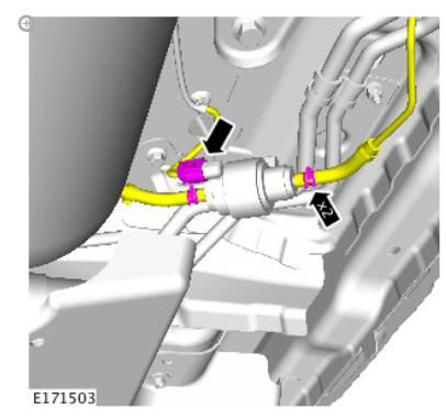

Torque: 10 Nm
INSTALLATION
- To install, reverse the removal procedure.
Auxiliary climate control fuel fired booster heater receiver unit (G1429610) removal and installation
REMOVAL
NOTE:
Removal steps in this procedure may contain installation details.
- Refer to: Parking Aid Module (413-13, Removal and Installation).

INSTALLATION
To install, reverse the removal procedure.
Auxiliary Climate Control
Evaporator and Blower
Motor Assembly (G1817039)
/ Removal and InstallationAuxiliary Climate ControlДополнительный климат-контрольAuxiliary Climate Control
COMPONENT LOCATION
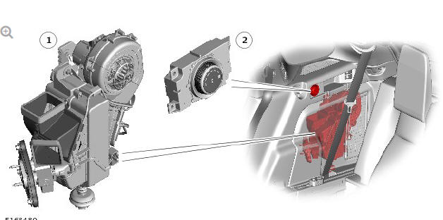
- Auxiliary climate control unit
- Fan speed control
OVERVIEW
The vehicle features a choice of air conditioning systems, with new features available to enhance the performance for second and third row seat passengers.
The system is available in two forms, with an optional rear air conditioning unit:
- Manual air conditioning system
- 2-zone climate control system, with separate LCD display controls for the driver and front passenger.
Vehicles with 5+2 seating have an optional auxiliary air conditioning unit for third row passengers, with a control for fan speed. Depending on the level of climate fitted to the vehicle the rear air conditioning temperature is controlled from the Touch Screen:
- On vehicles with dual zone climate - Climate > Rear A/C
- On vehicles with single zone manual climate - Home > Extra features > Rear A/C.
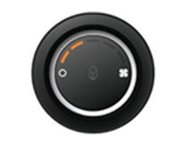
The rear air conditioning has a child lock function which disables the rear fan speed control switches. This is feature is accessed from the Touch Screen.
Third seats - fan speed control
DESCRIPTION
The auxiliary climate control assembly is installed on the right side of the luggage compartment, behind the rear quarter trim panel.
The air conditioning system includes the following features:
- B-pillar mounted mid-level vents for row 2 passengers
- Face-level vents mounted in the C-pillar on vehicles with 5+2 seating, for row 3 passengers
- A mist sensor on the windscreen, used to detect conditions likely to cause misting
- An air quality sensor for detection of pollutant levels. When levels exceed set limits the system switches to re-circulation mode
- ECO mode enables the system to adopt a more economical operating mode.
Air Conditioning Layout with Optional Independent Rear Air Conditioning Unit

- B-pillar mounted mid-level vents for row 2 passengers
- Face-level vents mounted in the C-pillar on vehicles with 5+2 seating, for row 3 passengers
- Optional independent air conditioning unit.
OPERATION
Air Conditioning Refrigerant Circuit With Optional Auxiliary Rear Air Conditioning Unit
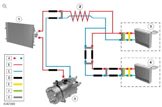
- Condenser
- Internal heat exchanger
- Front evaporator
- Rear evaporator
- 5 Compressor
- Joints B High pressure side C Low pressure side D Hose E Sealed system F Thermal expansion valve G Block connector
Auxiliary Climate Control
Fuel Fired
Booster Heater
Fuel Pump (G1791379)
/ Removal and InstallationAuxiliary Climate Control
Electric Booster
HeaterДополнительный климат-контроль электрический усилитель отопительAuxiliary Climate Control Electric Booster Heater
COMPONENT LOCATION

- Climate control assembly
- Electric booster heater
OVERVIEW
Due to the slower warm up times associated with some engines, an electric booster heater may be fitted to increase heater performance. The electric booster heater does this by heating the air leaving the coolant heat exchanger assembly. The electric booster heater comprises ceramic coated thermistor elements and a micro-controller. A request for electric booster heater operation originates in the Automatic Temperature Control Module (ATCM). This request is in the form of a Pulse Width Modulation (PWM) percentage and is transmitted to the electric booster heater microcontroller.
The amount of heating requested by the ATCM is based on:
- Ambient air temperature.
- Engine coolant temperature.
- Heating request.
NOTE:
There is also a minimum blower-motor speed required for the electric booster heater operation.
The electric booster heater is limited to 1.25kW. If electrical load management is in force, electric booster heater performance will be reduced.
DESCRIPTION
ELECTRIC BOOSTER HEATER

The electric booster heater is installed in the climate control assembly, on the downstream side of the heater core. It consists of ceramic coated Positive Temperature Coefficient (PTC) thermistor elements, rated at 1.25kW, and a micro-controller. Electrical power for the booster heater is supplied via a 100A megafuse. The CJB provides the electric booster heater with ignition feed also, by the ignition relay and a 5A fuse. Operation of the electric booster heater is controlled by the Automatic Temperature Control Module (ATCM).
OPERATION
GENERAL
The electric booster heater consists of a matrix, containing ceramic coated PTC elements, which is installed in the climate control assembly. On vehicles without an electric booster heater, a baffle plate is installed in place of the booster heater.
Operation of the electric booster heater is activated by the ATCM using Pulse Width Modulation (PWM) signal. The ATCM uses the following inputs from the Controller Area Network (CAN) bus, to control operation of the electric booster heater:
- Climate control system selections from the ATCM and the Touch Screen (TS), through the Medium Speed (MS) CAN Comfort and Body buses, via the GateWay Module (GWM).
- Ambient air temperature and engine coolant temperature from the Engine Control Module (ECM) via the HS CAN Powertrain bus
The ATCM requests operation of the electric booster heater, provided the vehicle is not in transit mode and there are no generator faults recorded, when the following conditions occur:
- The engine is running.
- The blower is on (any speed).
- Heating is requested on the ATCM, or on the menu of the Touch Screen, and the desired vent temperature (calculated by the ATCM), is not being achieved.
- The ambient air temperature is less than 10ºC (50ºF).
- The engine coolant temperature is less than 90ºC (194ºF).
- Battery charge state is more than 10A.
The duration of the PWM pulses requested by the ATCM is proportional to the amount of heating required.
If the electrical load management is in force, the electric booster heater performance is reduced by the modification of the PWM signal.
For additional information, refer to: Generator (414-02A Generator and Regulator - TD4 2.2L Diesel, Description and Operation).
The ATCM discontinues request of operation of the electric booster heater if the ambient temperature increases to 15ºC (59ºF), or any of the other required conditions ceases to exist.
The ATCM monitors the control circuits of the electric booster heater and records a Diagnostic Trouble Code (DTC) if it detects a short or open circuit.
CONTROL DIAGRAM

NOTE: A = HARDWIRED, O = LOCAL INTERCONNECT NETWORK (LIN) BUS; AN = HIGH SPEED (HS) CONTROLLER AREA NETWORK (CAN) POWERTRAIN BUS; AO = MEDIUM SPEED (MS) CAN BODY BUS; AP = MS CAN COMFORT BUS.
- Automatic Temperature Control Module (ATCM)
- Engine Control Module (ECM)
- Gateway Module (GWM)
- Touch Screen (TS)
- Generator
- Ground
- Power supply
- Electric booster heater
- Engine Junction Box (EJB)
- Battery
- Ambient Air Temperature (AAT) sensor
- Engine Coolant Temperature (ECT) sensor
- Battery Monitoring System (BMS) control module
Auxiliary Climate ControlAuxiliary Climate Control
Fuel Fired
Booster HeaterДополнительный климат-контроль топливо с приводом усилитель отопительAuxiliary Climate Control Fuel Fired Booster Heater
COMPONENT LOCATION - FUEL FIRED BOOSTER HEATER WITHOUT REMOTE CONTROL

- Integrated Control Panel (ICP) with Automatic Temperature Control Module (ATCM)
- Ambient Air Temperature (AAT) sensor
- Fuel Fired Booster Heater - fuel pump.
- Fuel Fired Booster Heater - coolant pump
- Fuel Fired Booster Heater (FFBH)
COMPONENT LOCATION - FUEL FIRED BOOSTER HEATER WITH REMOTE CONTROL

- Integrated Control Panel (ICP) with Automatic Temperature Control Module (ATCM)
- Ambient Air Temperature (AAT) sensor
- Fuel Fired Booster Heater - fuel pump.
- Fuel Fired Booster Heater - receiver
- Fuel Fired Booster Heater - antenna amplifier
- Fuel Fired Booster Heater - coolant pump
- Fuel Fired Booster Heater (FFBH)
OVERVIEW
The Fuel Fired Booster Heater (FFBH) is rated at 5kW and compensates for the relatively low-coolant temperatures inherent in the engine. The unit is located behind the right front fender splash shield and heats engine coolant upstream of the heater core.
Operation of the FFBH is controlled by the Automatic Temperature Control Module (ATCM) via a Local Interconnect Network (LIN) bus connection. The operation of the FFBH is influenced by:
- Ambient air temperature.
- Engine coolant temperature.
The FFBH will operate in supplementary mode if the ambient air temperature is lower than 5ºC (41ºF) and stop if ambient temperature reaches 8ºC (46ºF), or will provide a level of heating to the cabin or engine if the ambient is below 15ºC upon a user request by either the:
- FFBH remote control,
- timed climate,
- or TS (Touch Screen).
Operation of the FFBH may also be inhibited if the fuel level drops below a predetermined level.
DESCRIPTION
INTEGRATED CONTROL PANEL WITH AUTOMATIC TEMPERATURE CONTROL MODULE

The Integrated Control Panel (ICP) is mounted in the center console and contains the Automatic Temperature Control Module (ATCM). The ATCM works in conjunction with the Engine Control Module (ECM) to control all aspects of heating, ventilation, and Air Conditioning (A/C).
For additional information, refer to: Control Components (412-01 Climate Control, Description and Operation).
- Fuel Fired Booster Heater - Fuel Pump
- Sectioned View of Typical Fuel Fired Booster Heater
- Remote Control Components
- Auxiliary Climate Control Fuel Fired Booster Heater - Operation
Auxiliary Climate Control
Electric Booster
HeaterFuel Fired Booster
Heater - Fuel
PumpТопливо с приводом усилитель отопитель - топливо насосFuel Fired Booster Heater - Fuel Pump
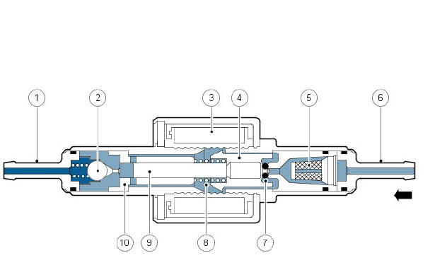
- Fuel line connector
- Non return valve
- Solenoid coil
- Plunger
- Filter insert
- Fuel line connector
- O-ring seal
- Spring
- Piston
- Bush
The Fuel Fired Booster Heater (FFBH), fuel pump is mounted adjacent to the fuel tank and regulates the fuel supply to the FFBH. The pump is a selfpriming, solenoid operated plunger pump, controlled by a Pulse Width Modulation (PWM) signal from the control module in the FFBH. When the pump is de-energized, it provides a positive shut-off of the fuel supply.
The solenoid coil of the fuel pump is installed around a housing which contains a plunger and piston. The piston locates in a bush, and a spring is installed on the piston between the bush and the plunger. A filter insert and a fuel line connector are installed in the inlet end of the housing. A nonreturn valve and a fuel-line connector are installed in the fuel outlet end of the housing.
While the solenoid coil is de-energized, the spring holds the piston and plunger in the closed position at the inlet end of the housing. An O-ring seal on the plunger provides a fuel tight seal between the plunger and the filter insert, preventing any flow through the pump. When the solenoid coil is energized, the piston and plunger move towards the outlet end of the housing, until the plunger contacts the bush; fuel is then drawn in through the inlet connection and filter. The initial movement of the piston also closes transverse drillings in the bush and isolates the pumping chamber at the outlet end of the housing. Subsequent movement of the piston then forces fuel from the pumping chamber through the non-return valve and into the line to the fuel fired booster heater. When the solenoid de-energizes, the spring moves the piston and plunger back towards the closed position. As the piston and plunger move towards the closed position, fuel flows past the plunger and through the annular gaps and transverse holes in the bush to replenish the pumping chamber.
Fuel fired booster heater

The Fuel Fired Booster Heater (FFBH) is installed in the coolant supply line to the climate control assembly and is located behind the front-right fender.
One electrical connector connects the FFBH to the vehicle wiring.
The FFBH comprises the following:
- Combustion air fan
- Burner housing
- Heat exchanger
- Air inlet hose and muffler
- Exhaust pipe and muffler
- Control module.
Auxiliary Climate Control
Fuel Fired
Booster HeaterSectioned View of Typical
Fuel Fired
Booster HeaterSectioned обзор Typical топливо с приводом усилитель отопительSectioned View of Typical Fuel Fired Booster Heater

- Combustion air fan
- Coolant inlet
- Coolant outlet
- Burner insert
- Heat exchanger
- Overheat temperature sensor
- Exhaust
- Fuel inlet
- Evaporator
- Air inlet
COMBUSTION AIR FAN
The combustion air fan regulates the flow of air into the FFBH to support combustion of the fuel supplied by the FFBH fuel pump. It is also used to purge and cool the FFBH.
BURNER HOUSING
The burner housing contains the burner insert and also incorporates connections for the exhaust pipe, the coolant inlet from the auxiliary coolant pump and the coolant outlet to the vehicle heater.
The burner insert incorporates the fuel combustion chamber, an evaporator and a glow pin and flame sensor. Fuel from the FFBH fuel pump is supplied to a metal mesh, where it evaporates and enters the combustion chamber to mix with air from the combustion air fan. The glow pin and flame sensor provides the ignition source for the fuel-air mixture and, once combustion is established, monitors the flame.
HEAT EXCHANGER
The heat exchanger transfers heat generated by combustion to the coolant.
Two sensors are installed in the heat exchanger casing to provide the control module with inputs of engine coolant temperature. The control module uses the temperature inputs to control system operation.
AIR INLET HOSE AND MUFFLER
A canister type muffler is included in the air inlet supply line. The muffler reduces the noise caused by induction roar and acts as a water separator to protect the FFBH in the event of water ingress.
EXHAUST PIPE AND MUFFLER
The exhaust pipe and muffler directs exhaust combustion gases to atmosphere below the front right wheel arch. Exhaust vapor may be visible when the FFBH is running, depending on atmospheric conditions.
FUEL FIRED BOOSTER HEATER CONTROL MODULE
The Fuel Fired Booster Heater Control Module (FFBHCM) controls and monitors operation of the FFBH system. An internal flow of air from the combustion air-fan ventilates the control module to prevent it from overheating.
The FFBHCM is powered by a permanent feed from the Battery Junction Box (BJB) through the Quiescent Current Control Module (QCCM). The FFBHCM communicates with the Automatic Temperature Control Module (ATCM) over the Local Interconnect Network (LIN) bus.
Auxiliary coolant pump

The auxiliary coolant pump is mounted on the bulkhead panel in the engine compartment and is used to assist coolant flow through the FFBH and the heater core.
The auxiliary coolant pump runs continuously while the FFBH is active.
When the FFBH is inactive, coolant flow is reliant on the engine coolant pump. Operation of the auxiliary coolant pump is controlled by a powerfeed direct from the control module within the FFBH.
Stop/Start System
During a Stop/Start cycle when the engine is shutdown and consequently the engine-driven coolant pump is stationary, the desired set cabin temperature cannot be maintained for a prolonged period, especially in cold ambient temperatures. To counteract this, the FFBH auxiliary electric coolant-pump (when fitted), controlled by the ECM, is used to maintain the coolant flow through the cabin's heater core. This supporting circulation prolongs the set temperature setting in the cabin and accordingly prevents an early engine restart.
AMBIENT AIR TEMPERATURE SENSOR

The Ambient Air Temperature (AAT) sensor is a Negative Temperature Coefficient (NTC) thermistor, and is mounted in the passenger door mirror.
The sensor is connected to the ECM, which broadcasts an ambient air temperature value over the HS CAN Powertrain bus. This value is received by the Central Junction Box (CJB) over the HS CAN Powertrain bus, and this value is transmitted into the ATCM over the MS CAN Comfort bus, via the GWM.
Fuel Fired Booster
Heater - Fuel
PumpRemote Control ComponentsДистанционный управление компонентыRemote Control Components
The remote control system comprises of the following components:
- FFBH
- FFBH remote control
- FFBH receiver
- Antenna and antenna amplifier
- Antenna harness to connect receiver co-axial cable to existing DAB antenna in side window.
Fuel Fired Booster Heater - Remote Control
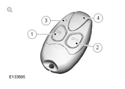
- On button
- Off button
- LED operation indicator
- Antenna
The remote control allows the driver to remotely activate the FFBH without entering the vehicle. The remote control has a range of at least 100m (328ft) in free space, although this distance may be decreased depending on the location of obstacles such as buildings. The remote control is powered by a 3.3volt CR1/3N replaceable battery which can be accessed by removing a cover from the rear of the remote control. The battery life in the remote control is approximately 300 FFBH cycles. One cycle is defined as a remote control button press followed by 30 minute burn time with flashing LED feedback.
The remote control has a green LED to indicate the FFBH is active. When the 'ON' button is pressed on the remote control for more than 2 seconds, the LED will illuminate for 2 seconds. After the 2 second period has passed, the LED will illuminate for 50ms every 2 seconds for up to the 30 minute on time of the FFBH. The LED will only stop flashing if the 'OFF' button is pressed or the 30 minute on timer has elapsed.
Remote Control LED Indicator Functionality
The LED illuminates in different ways to alert the driver to the various states of the FFBH remote control system as follows:
- Illuminates green for 2 seconds when the ON button has been pressed to show that the receiver unit has successfully received the remote control on request. The FFBH may now start operating providing that fuel level, battery voltage and coolant temperature variables are within limits
- Flashes green for 50 ms every 2 seconds to indicate that the FFBH may be active.
- Illuminates red for 2 seconds when the OFF button has been pressed to show that the receiver unit has successfully received the remote control off request. The FFBH should then stop operating.
- Flashes green or red for 2 seconds when pressing the ON or OFF buttons to indicate that the signal was not received by the FFBH receiver.
- Illuminates orange before changing to green or red to show that remote control battery voltage is low.
- Flashes orange for 5 seconds to show that signal was not received by the FFBH and that the remote control battery requires replacement.
Remote Control Pairing
Each remote control must be 'paired' to the receiver to enable communications. Each remote control has a unique identification number which is stored by the receiver. The receiver can store up 3 remote control identification numbers. If a fourth remote control is paired to the receiver, the receiver will replace the first paired remote control number with that for the fourth remote control in the receiver memory. Subsequently, the first paired remote control will no longer be paired and will not be recognized by the receiver.
The following procedure details the pairing process:
- Remove fuse F7 from the RJB
- Wait for a minimum of 5 seconds
- Replace fuse to position F7 in the RJB
- Within 5 seconds of replacing the fuse (and restoring the receiver power supply), press and hold the remote control OFF button
- Confirmation of successful pairing is displayed by the remote control LED illuminating in a red color for 2 seconds
NOTE: The pairing process relies on the FFBH receiver having the power supply removed and then the power supply re-instated. The fuse method is the easiest method but it can also be achieved by battery disconnection or removal of the harness connector from the receiver unit.
Fuel Fired Booster Heater - Receiver

The receiver is located in the left side of the luggage compartment. The receiver is mounted on an integral bracket which in turn is attached to the audio system bracket which locates the gold plated TV antenna.
The receiver is connected to the antenna on the left side window with a coaxial cable. RF signals from the remote control are received by the antenna and passed via the antenna matching unit and co-axial cable to the receiver.
The receiver processes the signals and transmits appropriate messages to the FFBH on a dedicated bus.
Antenna and Antenna Amplifier

The FFBH antenna is located in the rear left side window and uses the same antenna elements as used by the gold plated TV antenna system.
The antenna amplifier, a flying lead from this unit connects directly to a stud on the glass antenna. The receiver unit connects to the amplifier via a coaxial cable.
The glass mounted antenna receives RF transmitted signals from the remote control and transmits them, via the amplifier and co-axial cable, to the FFBH receiver.
Sectioned View of Typical
Fuel Fired
Booster HeaterAuxiliary Climate Control
Fuel Fired
Booster Heater - OperationДополнительный климат-контроль топливо с приводом усилитель отопитель - работаAuxiliary Climate Control Fuel Fired Booster Heater - Operation
If a heating request is received and the ambient air temperature is less than or equal to 5ºC (41ºF), the Automatic Temperature Control Module (ATCM) transmits a 'supplemental heat' message to the Fuel Fired Booster Heater Control Module (FFBHCM) on the LIN bus. The control module responds by returning a 'supplemental heat' status message back to the ATCM. The control module will now initiate the Fuel Fired Booster Heater (FFBH) start sequence.
If the heating request is removed, or ambient air temperature rises to 8ºC (46ºF), the ATCM transmits a 'heater off' message to the FFBHCM on the LIN bus. Again, the FFBHCM responds by returning a 'heater off' status message back to the ATCM. The control module will now de-activate the FFBH.
If maximum heating is requested, ECM becomes the overriding factor. In this instance, the ATCM will change the LIN bus message from 'heater off' to 'supplemental heat' when engine coolant temperature measured by the FFBH is below or equal to 70ºC (158ºF). If the engine coolant temperature measured by the FFBH rises to 78ºC (172ºF) the ATCM returns the message to 'heater off'.
The FFBHCM will not start the FFBH, or will discontinue operation, if any of the following occur:
The FFBHCM is in the error lockout mode (see Diagnostics below)
The engine is not running, or stops running for approximately 4 seconds.
The time delay is included for stall detection
- 'fuel A cut-off' message is received from the CJB over the MS CAN Body and Comfort bus via the GWM.
For additional information, refer to: Electronic Engine Controls (303-14A Electronic Engine Controls - TD4 2.2L Diesel, Description and Operation).
A low fuel level message is received from the CJB over the MS CAN Comfort and Body bus via the GWM (see table below).
For additional information, refer to: Fuel Tank and Lines (310-01A Fuel Tank and Lines - TD4 2.2L Diesel, Description and Operation).
- If the supply voltage is above/below the required threshold.
The FFBHCM will control FFBH operation based on the following levels of fuel in the tank.
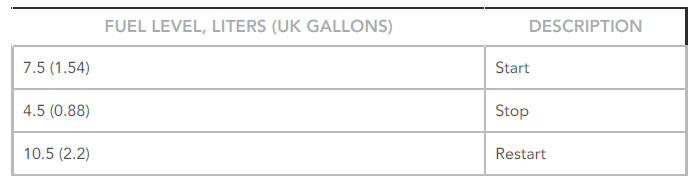
Start Sequence
At the beginning of a start sequence, the Fuel Fired Booster Heater Control Module (FFBHCM):
- energizes the glow pin and flame sensor to pre heat the combustion chamber,
- starts the combustion air fan at slow speed,
- and energizes the auxiliary coolant pump.
After approximately 30 seconds, the FFBHCM energizes the auxiliary fuel pump at the starting sequence speed. The fuel delivered by the auxiliary fuel pump evaporates in the combustion chamber, mixes with air from the combustion air fan and is ignited by the glow pin and flame sensor. The FFBHCM then progressively increases the speed of the auxiliary fuel pump and the combustion air fan. Once combustion is established the control module switches the glow pin and flame sensor to the flame sensing function to monitor combustion. From the beginning of the start sequence to stable combustion at full load takes approximately 150 seconds.
FULL AND PART LOAD COMBUSTION
While the FFBH is running, the Fuel Fired Booster Heater Control Module (FFBHCM) cycles the heater between full load combustion, part load combustion (available for vehicles with Diesel engine) and a control idle phase of operation, depending on the temperature of the coolant in the FFBH heat exchanger.
The heat output level at part load combustion is 2.5kW. This rises to 5kW at full load combustion. The FFBHCM transmits the amount of fuel used by the FFBH to the Instrument Cluster (IC), and the FFBH coolant temperature to the ATCM.
Switching Point Temperatures
NOTE:
Vehicles with Diesel engine.


After the start sequence, the FFBHCM maintains full load combustion until the coolant temperature reaches switching point temperature 1. At this temperature, the FFBHCM decreases the speed of the auxiliary fuel pump and the combustion air fan to half speed, to produce part load combustion.
The FFBHCM maintains part load combustion while the coolant temperature remains between switching point temperatures 2 and 4. At part load combustion the temperature of the coolant will increase or decrease depending on the amount of heat required to heat the vehicle interior. If the coolant temperature decreases to switching point temperature 4, the FFBHCM increases the speed of the auxiliary fuel pump and the combustion air fan to full speed, to return to full load combustion. If the coolant temperature increases to switching point temperature 2, the FFBHCM enters a control idle phase of operation.
On entering the control idle phase, the FFBHCM immediately switches the auxiliary fuel pump off, to stop combustion, and starts a timer for the combustion air fan. After a 2 minute cool down period, the FFBHCM switches the combustion air fan off and then remains in the control idle phase while the coolant temperature remains above switching point temperature 3. If the coolant temperature decreases to switching point temperature 3, the FFBHCM initiates a start to part load combustion. A start to part load combustion takes approximately 90 seconds.
In order to limit the build-up of carbon deposits on the glow pin and flame sensor, the FFBHCM also enters the control idle phase if continuous combustion time exceeds 72 minutes (at part load, full load or a combination of both). After the cool down period, if the coolant is still in the temperature range that requires additional heat, the FFBHCM restarts the fuel fired booster heater.
SHUTDOWN
To stop the FFBH, the FFBHCM de-energizes the auxiliary fuel pump to stop combustion, but continues operation of the combustion air fan and the auxiliary coolant pump for a time, to cool down the FFBH. The cool down time is 100 seconds if the FFBH was operating at part load combustion and 175 seconds if the FFBH was operating at full load combustion.
DIAGNOSTICS
The Fuel Fired Booster Heater Control Module (FFBHCM) monitors the fuel fired booster heater system for faults. The Diagnostic Trouble Codes (DTC) are stored in a volatile memory in the FFBHCM, which can be interrogated by the Land Rover approved diagnostic system via the MS CAN Comfort bus.
The FFBHCM also incorporates an error lockout mode of operation that inhibits operation to prevent serious faults from causing further damage to the system. In the error lockout mode, the FFBHCM immediately stops the FFBH fuel pump, and stops the combustion air fan and auxiliary coolant pump after a cool down time of approximately 2 minutes. Error lockout occurs for:
- Start failure and flameout: If a start sequence fails to establish combustion, or a flameout occurs after combustion is established, the Fuel Fired Booster Heater Control Module (FFBHCM) immediately initiates another start sequence. The start failure or flameout is also recorded by an event timer in the FFBHCM. The event timer is increased by one after each start failure, flameout, and FFBH component failure, and will set back to zero if a subsequent start is successful. If the event timer increases to six (over any number of drive cycles), the FFBHCM enters the error lockout mode.
- Heat exchanger casing overheat: To protect the system from excessive temperatures, the Fuel Fired Booster Heater Control Module (FFBHCM) enters the error lockout mode if the heat exchanger coolant temperature exceeds 125ºC (257ºF).
The error lockout mode can be cleared using the Land Rover approved diagnostic system, or by disconnecting the battery power supply for a minimum of 10 seconds.
REMOTE OPERATION
The remote system includes the addition of a Fuel Fired Booster Heater (FFBH) receiver, FFBH antenna and a remote control for operation of the system. The FFBH unit remains as previously fitted. The IC message center displays FFBH messages when required.
The 868.3MHz RF signals transmitted by the remote control are received by the TV/FFBH antenna located in the rear left side window. The signals received by the antenna are detected by the FFBH receiver. A 'handshake' signal is sent back from the receiver to the remote control to confirm a valid on or off request and activate the remote control Light Emitting Diode (LED) accordingly. The receiver processes the signal it received and transmits the appropriate signals via a dedicated bus to the Fuel Fired Booster Heater Control Module (FFBHCM).
NOTE:
NOTE: The 'handshake' signal only confirms remote control-receiver communications were successful, and not that the FFBH has turned on.
When the FFBH is activated by the remote control, the FFBHCM will allow the FFBH to operate for 30 minutes or until an off request is received from the remote control or CJB. During the 30 minute period, the FFBH may operate in either full load combustion, part load combustion or a controlled idle phase of operation, depending on the temperature of the coolant in the heat exchanger.
PRE-BURN THRESHOLDS
The FFBH unit will only activate remotely if the following threshold conditions are met:
- Pre-burn battery voltage check: ≥11.5V (voltage at FFBH terminals)
- Pre-burn coolant temperature check: ≤15ºC (internal FFBH measurement)
- Pre-burn fuel level check: ≥7.5 liters (value stored in FFBH at ignition off)
The fuel level value stored within the FFBH unit is only updated when the engine is running. When starting the FFBH via remote control with the engine off, the fuel level value used in the FFBH calculations will be that stored at the last key off event. It is therefore possible for the FFBH to fail to operate remotely if the engine was stopped with a low fuel level; if the fuel tank is subsequently refueled, the FFBH stored fuel level will still read low if the engine has not been started since refueling.
If the FFBH does not activate due to low battery voltage or low fuel level, the Fuel Fired Booster Heater Control Module (FFBHCM) transmits a message on the LIN bus to the IC message center, which will display one of the following messages at ignition on:
- AUXILIARY HEATER UNAVAILABLE LOW FUEL
- AUXILIARY HEATER UNAVAILABLE LOW BATTERY
If both low fuel and low battery voltage messages are valid, the instrument cluster message center will alternate between the two messages.
REMOTE CONTROL 'PARK HEAT' TO ATCM 'SUPPLEMENTARY HEAT' TRANSITIONS
NOTE:
The FFBH can still be activated by the ATCM as previously described.
If the FFBH has been operated remotely ('park heat') and the vehicle is started whilst the FFBH is still active, it will transition into the ATCMcontrolled 'supplementary heat' mode if the ATCM requests it.
Should the ATCM then send a message to the FFBH to turn off, the FFBH will remain active if 30 minutes has not yet elapsed from the original remote control 'park heat' request. Once the remainder of 30 minutes has elapsed, the FFBH will turn off.
Switching Point Temperatures
NOTE: Vehicles with Diesel engine.
When remotely started the FFBH uses a different set of switching point temperatures to the normal 'supplemental heat' mode. This is because the remote start feature can start the FFBH with the engine off - thus different thresholds are required to optimize the heating of the engine coolant.
Switching Point Temperatures


Auxiliary climate control specifications
Torque Specifications

Remote Control ComponentsClimate Control Air
Conditioning Compressor - Ingenium I4 2.0l
Diesel
(G1885406)/ Removal and
InstallationКлимат-контроль кондиционирование воздуха Compressor - Ingenium I4 2.0l дизель / снятие и установкаClimate Control Air Conditioning Compressor - Ingenium I4 2.0l Diesel (G1885406)/ Removal and Installation
REMOVAL
- Disconnect the battery ground cable.
Refer to: Specifications (414-01 Battery, Mounting and Cables, Specifications).
WARNING:
Make sure to support the vehicle with axle stands.
Raise and support the vehicle.
Refer to: Air Conditioning System Recovery, Evacuation and Charging - INGENIUM I4 2.0L Diesel (412-00 Climate Control System - General Information, General Procedures).
Refer to: Engine Undershield (501-02 Front End Body Panels, Removal and Installation).
Refer to: Accessory Drive Belt (303-05B Accessory Drive - INGENIUM I4 2.0L Diesel, Removal and Installation).
CAUTIONS:
- Before disconnecting any components, make sure the area is clean and free from foreign material. When disconnected all openings must be sealed.
- Lubricate the new seals with clean refrigerant oil.
NOTE:
Install new O-ring seals.

Torque: 25 Nm


Torque: 25 Nm
INSTALLATION
- To install reverse the removal procedure.
Climate control air conditioning pressure transducer (G1815596) removal and installation
REMOVAL
WARNING:
Wear safety goggles and protective gloves.
NOTES:
- Removal steps in this procedure may contain installation details.
- Some variation in the illustrations may occur, but the essential information is always correct.
Refer to: Plenum Chamber (412-01 Climate Control, Removal and Installation).
CAUTIONS:
- Extreme cleanliness must be exercised when handling these components.
- Before disconnecting any components, make sure the area is clean and free from foreign material. When disconnected all openings must be sealed.

Torque: 8 Nm
INSTALLATION
- To install, reverse the removal procedure.
Auxiliary Climate Control
Fuel Fired
Booster Heater - OperationClimate Control - Air
ConditioningКлимат-контроль - кондиционирование воздухаClimate Control - Air Conditioning
COMPONENT LOCATION - VEHICLES WITHOUT AN INTERNAL HEAT EXCHANGER ( IHX )

- Refrigerant pressure sensor
- Thermostatic eXpansion Valve (TXV)
- Evaporator
- Receiver/Drier
- Condensor
- Air Conditioning (A/C) compressor
- Low pressure line
- High pressure line
- Low pressure servicing connection
- High pressure servicing connection
COMPONENT LOCATION - VEHICLES WITH AN INTERNAL HEAT EXCHANGER ( IHX )

- Refrigerant pressure sensor
- Thermostatic eXpansion Valve (TXV)
- Evaporator
- Receiver/Drier
- Condensor
- Air Conditioning (A/C) compressor
- Low pressure line
- High pressure line
- Low pressure servicing connection
- High pressure servicing connection
Overview
A choice of Air Conditioning (A/C) systems are available with features to enhance the performance for second and third-row seat passengers.
The system is available in two forms, with an optional rear air conditioning unit.
- Manual air conditioning system.
- Two-zone auto system, with separate LCD display controls for driver and front passenger.
- Vehicles with 5+2 seating, an optional auxiliary air conditioning unit
for
third row passengers is available, with controls for temperature and fan
speed.
For additional information, refer to: Auxiliary Climate Control (412-02 Auxiliary Climate Control, Description and Operation).
The rear air conditioning has a child lock function which disables the rear fan speed control switches. This is feature is accessed from the Touch Screen.
The A/C system transfers heat from the passenger compartment to the outside atmosphere to provide the climate control assembly with dehumidified cool air.
The A/C system is a sealed closed-loop system, filled with refrigerant as the heat transfer medium. Refrigerant oil is added to the refrigerant to lubricate the internal components of the A/C compressor:
- R1234yf refrigerant is used in USA and Canada (NAS market); systems with an Internal Heat Exchanger (IHX) installed.
- R134a refrigerant is used in the ROW markets; systems without an Internal Heat Exchanger (IHX).
For additional information, refer to: Specifications (412-01 Climate Control, Specifications).
The compressor is a variable displacement unit, where the displacement (flow of refrigerant) is controlled to match the thermal load of the evaporator. The type of compressor fitted will depend on engine variant, see below.
The operation of the A/C system is controlled by the Automatic Temperature Control Module (ATCM).
For additional information, refer to: Control Components (412-01 Climate Control, Description and Operation).
- Climate Control - Air Conditioning / Description
- Climate Control - Air Conditioning/ Operation
Climate Control Air
Conditioning Compressor - Ingenium I4 2.0l
Diesel
(G1885406)/ Removal and
InstallationClimate Control - Air
Conditioning / DescriptionКлимат-контроль - кондиционирование воздуха / описаниеClimate Control - Air Conditioning / Description
DESCRIPTION
The air conditioning system includes the following features:
- B-pillar mounted mid-level vents for row 2 passengers
- Face-level vents mounted in the C-pillar on vehicles with 5+2 seating, for row 3 passengers
- A mist sensor on the windscreen, used to detect conditions likely to cause misting
- An air quality sensor for detection of pollutant levels. When levels exceed set limits the system switches to re-circulation mode
- Timed climate control to pre-heat the cabin. This function can be activated remotely using the InControl Remote App
- ECO mode enables the system to adopt a more economical operating mode.
Air Conditioning Layout with Optional Auxiliary Rear Air Conditioning Unit

- B-pillar mounted mid-level vents for row two passengers
- Face-level vents mounted in the C-pillar on vehicles with 5+2 seating, for row three passengers
- Optional auxiliary air conditioning unit
The optional auxiliary air conditioning unit is discussed in another section.
For additional information, refer to: Auxiliary Climate Control (412-02 Auxiliary Climate Control, Description and Operation).
AIR CONDITIONING COMPRESSOR
2.0 GTDi Petrol

- Pulley with electro-magnetic clutch
- Refrigerant inlet port
- Pressure relief valve
- Electronic control valve connector
- Refrigerant outlet port
- Electro-magnetic clutch connector.
TD4 2.2L Diesel
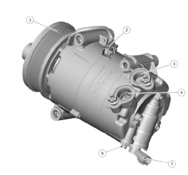
- Pulley with electro-magnetic clutch
- Electro-magnetic clutch connector
- Refrigerant outlet port
- Refrigerant inlet port
- Electronic control valve connector
- Pressure relief valve.
COMPRESSOR
The Air Conditioning (A/C) compressor is driven by the engine primary drive belt. The compressor circulates refrigerant around the A/C system by compressing low-pressure, low-temperature vapor from the evaporator and discharging the resultant high-pressure, high-temperature vapor to the condensor.
To protect the system from excessive pressure, a pressure relief valve is installed in the outlet side of the A/C compressor. The pressure relief valve vents excess pressure into the engine compartment.
Both compressors are variable displacement units. Displacement is controlled by an integral electronic control valve operated by the Automatic Temperature Control Module (ATCM). The control valve measures the input and output pressures of the refrigerant entering and leaving the compressor and controls the angle of the internal swash plate accordingly. The ATCM influences the control to match the thermal load of the evaporator and other factors.
Compressor clutch engagement is controlled by the ATCM.
For additional information, refer to: Control Components (412-01 Climate Control, Description and Operation).
CONDENSOR

- Condensor
- Receiver/drier
The condensor transfers heat from the refrigerant to the surrounding air to cool the refrigerant and therefore convert the high-pressure vapor from the compressor into a liquid. The condensor is installed immediately in front of the radiator.
The condensor is classified as a sub-cooling condensor and consists of a fin and tube heat-exchanger core installed between 2 end tanks. Divisions in the end tanks separate the heat exchanger into a 4 pass upper (condensor) section and a 2 pass lower (sub-cooler) section.
The right end tank provides the connections to the high-pressure line from the A/C compressor and the liquid line to the evaporator.
RECEIVER/DRIER
The receiver/drier is integral with the condensor left end-tank and removes solid impurities and moisture from the refrigerant. It also acts as a reservoir for liquid refrigerant to accommodate changes of heat load at the evaporator.
Refrigerant entering the receiver drier passes through a filter and a desiccant pack, then collects in the base of the unit before flowing through the outlet pipe back to the condensor.
REFRIGERANT PRESSURE SENSOR

The refrigerant pressure sensor provides the Automatic Temperature Control Module (ATCM) with a pressure input from the high-pressure side of the refrigerant system. The refrigerant pressure sensor is hardwired to the ATCM, which uses the signal to control operation of the A/C compressor through the A/C compressor clutch relay in the Battery Junction Box (BJB).
Additionally, the ATCM is able to increase the amount of re-circulated air, if it is required. The ATCM broadcasts the refrigerant high-pressure value over the medium-speed Controller Area Network (CAN) comfort bus to the Engine Control Module (ECM) via the Gateway Module (GWM). The ECM calculates the additional load on the engine when the A/C compressor is working. For example, this signal is used as an input, for the idle speed control.
The refrigerant pressure sensor is located in the refrigerant line between the condensor and the Thermostatic Expansion Valve (TXV).
THERMOSTATIC EXPANSION VALVE

- Metering valve
- Housing
- Diaphragm
- Temperature sensor
- Outlet passage from evaporator
- Inlet passage to evaporator.
The Thermostatic Expansion Valve (TXV) meters the flow of refrigerant into the evaporator to match the refrigerant flow with the heat-load of the air passing through the evaporator.
The TXV is a block type valve located behind the climate control assembly, and attached to the inlet and outlet ports of the evaporator. The TXV consists of an aluminum housing containing inlet and outlet passages. A ball and spring metering valve is installed in the inlet passage and a temperature sensor is installed in the outlet passage. The temperature sensor consists of a temperature sensitive tube connected to a diaphragm. The bottom end of the temperature sensitive tube acts on the ball of the metering valve.
Pressure on top of the diaphragm is controlled by the evaporator outlettemperature conducted through the temperature sensitive tube. The bottom of the diaphragm senses evaporator outlet pressure.
Liquid refrigerant flows through the metering valve into the evaporator. The restriction across the metering valve reduces the pressure and temperature of the refrigerant. The restriction also changes the liquid stream of refrigerant into a fine spray, to improve the evaporation process. As the refrigerant passes through the evaporator, it absorbs heat from the air flowing through the evaporator. The increase in temperature causes the refrigerant to vaporize and increase in pressure.
The temperature and pressure of the refrigerant leaving the evaporator acts on the diaphragm and temperature sensitive tube, which regulate the metering valve opening and so controls the volume of refrigerant flowing through the evaporator. The warmer the air flowing through the evaporator, the more heat available to evaporate refrigerant and thus the greater volume of refrigerant allowed through the metering valve.
EVAPORATOR

- Heater core
- Evaporator.
The evaporator is installed in the climate control assembly, between the blower and the heater core, to absorb heat from the exterior or recirculated air. Low pressure, low temperature refrigerant changes from liquid to vapor in the evaporator, absorbing large quantities of heat as it changes state.
Most of the moisture in the air passing through the evaporator condenses into water, which drains out of the vehicle by passing through a drain tube to the underside of the vehicle.
REFRIGERANT LINES
To maintain similar flow velocities around the A/C system the diameter of the refrigerant lines varies to suit the two pressure/temperature regimes.
Larger diameter pipes are installed in the low pressure/temperature regime and smaller diameter pipes are installed in the high pressure/temperature regime.
Nylon lined, low permeability rubber hoses are used in the low pressure line into the A/C compressor, and in the high pressure line from the condensor.
The remainder of the refrigerant lines are manufactured from aluminum.
Low and high pressure charging connections are incorporated into the refrigerant lines for system servicing.
INTERNAL HEAT EXCHANGER

- High pressure line
- Low pressure line
- Internal Heat Exchanger (IHX)
The Internal Heat Exchanger (IHX) is incorporated within the air conditioning pipes.
The IHX is part of the vehicle's air conditioning system and helps to increase its cooling capacity. The IHX combines a section of the system's pipework before and after the evaporator into one pipe. It uses the cold vapour exiting the evaporator to cool the hot liquid before it enters the expansion device, resulting in increased cooling. It also uses the heat to increase the temperature of the low temperature gas before it enters the compressor.
The amount of energy used by the air conditioning system can be reduced by taking advantage of this increased cooling.
This gives the following benefits:
- Helps reduce tailpipe CO2 emissions, due to less engine load
- Improved fuel economy, due to reduced compressor power requirements
- R1234yf - Increases the system capacity to increase cooling.
Climate Control - Air
ConditioningClimate Control - Air
Conditioning/ OperationКлимат-контроль - кондиционирование воздуха / работаClimate Control - Air Conditioning/ Operation
PRINCIPLES OF OPERATION
To accomplish the transfer of heat, the refrigerant is circulated around the system, where it passes through two pressure/temperature regimes. In each of the regimes the refrigerant changes state, during this process the maximum heat absorption or dissipation occurs.
The low pressure/temperature regime is from the TXV, then through the evaporator to the compressor. The refrigerant decreases in pressure and temperature at the TXV then changes state from a liquid to a vapour in the evaporator to absorb heat.
The high pressure/temperature regime is from the compressor, through the condensor and receiver drier assembly to the thermostatic expansion valve.
The refrigerant increases in pressure and temperature as it passes through the compressor; then releases heat and changes state from a vapour to a liquid in the condenser.
The operation of the A/C system is controlled by the ATCM.
For additional information, refer to: Control Components (412-01 Climate Control, Description and Operation).
NOTE:
NOTE: Due to a drop in performance of the R1234yf system when compared to the R134a system an Internal Heat Exchanger is installed
INPUT/OUTPUT DIAGRAM
System without an Internal Heat Exchanger (IHX)
NOTE:
NOTE: A = Refrigerant liquid; B = Refrigerant vapor; C = Air flow

- Evaporator
- TXV
- High pressure servicing connection
- Refrigerant pressure sensor
- Electric cooling fan
- Condensor
- Receiver/drier
- A/C compressor
- Low pressure servicing connection
- Blower
System with an Internal Heat Exchanger (IHX)
NOTE:
NOTE: A = Refrigerant liquid; B = Refrigerant vapor; C = Air flow

- Evaporator
- TXV
- High pressure servicing connection
- Refrigerant pressure sensor
- Electric cooling fan
- Condenser
- Receiver/Drier
- A/C compressor
- IHX
- Low pressure servicing connection
- Blower
Climate Control - Air
Conditioning / DescriptionElectronic Feature Group